Tray Cable on the Job: Picking TC, TC-ER, PLTC, and ITC for Long Island installs
Updated: August 21, 2025
TL;DR
Pick by circuit class and environment first, then by listing. Use TC for power and control, TC-ER for supported exposed drops, ITC for low-energy instrumentation, and PLTC for power-limited Class 2 or 3. Size conductors using 310.16 with termination limits from 110.14(C). For motors, apply 430.22 for conductors and 430.52 for overcurrent protection. Verify tray rules in Articles 392 and 336. Shield analog loops, bond shields correctly, label everything, and confirm adoption with the AHJ before buying long runs.
Why it matters
Choose tray cable well and you get reliable power, clean signals, fewer callbacks, and a smooth inspection. Choose poorly and you get noise, nuisance trips, and rework. If you need options fast, start here: tray and instrumentation cables.
Fundamentals
- Type TC is a general workhorse for power, lighting, control, and signaling. It is listed to UL 1277 and recognized by the NEC for trays, raceways, and some outdoor uses when marked appropriately. TC-ER extends this with “exposed run” privileges when you meet support and protection rules.
- Type ITC is Instrumentation Tray Cable for low-energy instrumentation and control circuits. In the 2023 NEC, ITC content resides in Article 335.
- PLTC serves power-limited Class 2 and Class 3 circuits. In 2023, Article 722 covers cables for power-limited and fault-managed power circuits. Class 4 fault-managed power systems are addressed in new Article 726.
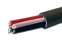
- Construction: conductor metal and stranding, insulation (PVC, XLPE), jacket (PVC, CPE, LSZH), shield (foil, braid, combo), and flame rating. Look for markings like sunlight resistant, oil resistant, direct burial, and “-ER” as needed. Browse common 600 V tray cable options to see how features vary by SKU.
Code & compliance (NEC 2023 references)
This is a road map, not quoted code text. Always verify with your local Authority Having Jurisdiction. Long Island towns, counties, and utilities may be on different adoption cycles, and New York City has its own amendments.
- Article 336 governs Type TC, including uses permitted, uses not permitted, and TC-ER exposed runs. Identification for wet, corrosive, and outdoor locations lives here too.
- Article 335 covers ITC. Keep the voltage and current limits for instrumentation circuits in mind during design.
- Article 722 covers cables for power-limited circuits and fault-managed power circuits. Article 726 covers Class 4 Fault-Managed Power Systems.
- Article 392 covers cable trays as a wiring support system, including which wiring methods may be installed in trays and basic fill concepts.
- 310.16 for ampacity, 110.14(C) for termination temperature ratings, 240.4(D) for small conductor protection, and 250 for grounding and bonding. For motors, apply 430.22 and 430.52.
If you need hardware for support and drops, see cable trays and strut supports and matching threaded rods and tray accessories.
Selection steps
- Confirm the circuit and environment. Is it power, control, instrumentation, or power-limited? Is the route indoors, outdoors, wet, oily, in sunlight, or in a corrosive area? If EMI is likely, plan on a shield and good bonding.
- Pick the listing and standard. For power and control, Type TC to UL 1277 is typical. Need to leave the tray to a motor or MCC? Consider TC-ER if you meet exposed-run rules in Article 336. For low-energy instrumentation, use ITC under Article 335. For Class 2 and 3, use PLTC under the cable rules in Article 722.
- Choose insulation, jacket, and shield. PVC is common and cost effective. XLPE handles higher temperature and often lower capacitance for long runs. For harsh chemicals or UV, pick a jacket with the correct oil, sunlight, and wet ratings. Foil shields help with high-frequency noise. Braid improves low-frequency rejection and durability. Combo shields give both.
- Set voltage, temperature, and conductor details. Match the cable voltage rating to the circuit, select the temperature rating that fits your termination limits per 110.14(C), and choose conductor size and count. You will check ampacity against 310.16 and the small-conductor rules in 240.4(D) during sizing.
- Verify the route against Articles 336 and 392. Confirm the wiring method is allowed in the tray, support spacing is adequate, and any exposed run complies with TC-ER rules. Keep separation in mind if trays carry mixed systems.
Sizing and configuration examples
Example 1: 480 V motor branch from tray to MCC using TC-ER
- Load: 56 A motor full-load current. Three current-carrying conductors in one cable. 90 C insulation, 75 C terminations per 110.14(C).
- Conductor size (430.22): Motor branch-circuit conductors must be at least 125% of motor FLC. 1.25 × 56 A = 70 A minimum ampacity. From Table 310.16, 4 AWG copper is 95 A at 90 C and 85 A at 75 C, which satisfies the 70 A minimum.
- OCPD (430.52, inverse-time circuit breaker): Start at 175% of FLC. 1.75 × 56 A = 98 A. Next standard size is 100 A per 240.6(A). This may exceed the conductor ampacity, which is permitted for motor circuits because the breaker provides short-circuit and ground-fault protection while overload protection is handled by the motor controller.
- Cable: Type TC-ER, 600 V, XLPE insulation for thermal margin, sunlight and oil resistant if exposed. Support and protect per Article 336 when the cable exits the tray. For a stocked example, see 4/3 tray cable with ground.
Example 2: 4-20 mA analog loop in a noisy pump room
- Circuit type: Instrumentation, power-limited. Choose PLTC or ITC based on the control system classification and route.
- Shield: Use a foil shield with drain wire for high-frequency noise. Bond the shield at one end only to avoid ground loops unless the device maker requires both ends bonded. Route away from VFD outputs in the tray. See control and instrumentation cables.
- Capacitance: For long loops, XLPE insulation helps with lower capacitance which preserves signal response.
Example 3: Outdoor compressor pad feed in tray
- Environment: Sunlight, wet, possible oil exposure. Select TC marked sunlight resistant and wet rated. If direct burial segments exist, the cable must be listed for that use.
- Hardware: Use listed tray and supports. See cable trays and strut supports and threaded rods and tray accessories.
Installation and wiring notes
- Routing: Confirm the cable type is permitted in the tray under Articles 392 and 336. Maintain reasonable separation between power and sensitive control circuits. Honor the manufacturer minimum bend radius.
- Exposed runs: TC-ER may exit a tray for a supported exposed run when all Article 336 conditions are met. Protect from physical damage at drops and terminations.
- Terminations: Land conductors on devices with temperature ratings that match your ampacity choice. If lugs are 75 C, use the 75 C ampacity from 310.16 even if the cable is 90 C rated.
- Bonding: Bond metallic armor and drain wires per Article 250 and the cable manufacturer. Avoid parallel shield bonds that create loops in analog circuits.
- Markings: Look for “sunlight resistant,” “wet,” “oil resistant,” “-ER,” and “direct burial” where needed. Do not assume every TC carries all of these.
Testing, commissioning, documentation
- Continuity: Verify all conductors, grounds, and shields ring out end to end before energizing.
- Insulation tests: For power conductors, use a megohmmeter at the manufacturer-recommended voltage. For instrumentation, use lower-voltage insulation checks to protect devices.
- Shield checks: Confirm shield bonding per design. If single point, verify the far end is isolated.
- Labeling: Tag cable IDs at each end and at tray transitions. Update as-builts with tray pathway, support intervals, and termination temperature ratings used in sizing.
- Sign off: Record test values, torque settings, and device firmware where relevant. Keep the packet for the AHJ and the owner.
Troubleshooting
- Analog noise on loops: Verify the shield type matches the environment. Bond the drain at one end only unless the device manual says otherwise. Separate from VFD outputs in the tray.
- Nuisance tripping or overheating: Recheck ampacity from 310.16 against termination ratings in 110.14(C). If terminations are 75 C, use the 75 C column even if the cable is 90 C rated.
- Intermittent faults outdoors: Look for UV cracking, water ingress at glands, or jackets not marked sunlight resistant or wet rated. Replace with the correct listing.
- Device communications dropouts: Inspect for crushed cable at exits, exceeded bend radius, or poorly supported TC-ER drops. Add supports and strain relief at the tray edge.
Common mistakes
- Assuming all TC is TC-ER. Exposed-run privileges apply only when marked and when Article 336 conditions are met.
- Using the wrong ampacity column for the termination rating.
- Mixing sensitive instrumentation pairs next to VFD outputs in the same tray without separation or shielding.
- Outdoor runs with jackets that are not sunlight or oil resistant.
- Skipping documentation of shield bond points.
Parts to stock + Shop at Revco
- Power and control TC or TC-ER in common sizes and conductor counts. Start with 600 V tray cable assortments for branch circuits and motor drops.
- Shielded instrumentation pairs for analog loops and sensor networks. See instrumentation and control options.
- Cable tray hardware for clean routing and reliable support. Stock tray and strut plus hangers and threaded rod accessories.
When to call the AHJ or an engineer
- Hazardous locations or corrosive processes.
- Long exposed runs using TC-ER where support methods are unusual.
- Mixed-voltage trays or shared pathways with communications or optical fiber.
- Class 4 or other limited-energy systems where Articles 722 and 726 interact with your tray wiring.
Local note: Long Island jurisdictions may be on different NEC editions or have amendments. Confirm adoption and any utility requirements before ordering cable.
Safety disclaimer
This article gives practical guidance and code references. It is not a substitute for the adopted code, the manufacturer’s instructions, or stamped engineering. The AHJ has final say. Follow lockout or tagout, PPE, and testing procedures at all times.
FAQ
- Can TC be used outdoors? Yes when marked sunlight resistant and wet rated. For direct burial, the cable must be listed for that use.
- What is the difference between TC and TC-ER? TC-ER is a TC cable with an exposed-run rating that allows a supported run outside raceway between the tray and equipment when Article 336 conditions are met.
- ITC vs PLTC? ITC serves low-energy instrumentation under Article 335. PLTC is for power-limited Class 2 and 3 circuits and is covered by the cable rules in Article 722.
- How do I size the conductors? Use 310.16 for ampacity and honor termination temperature ratings in 110.14(C). For motors, apply 430.22 for conductors and 430.52 for the OCPD.
- Do I always need a shield? No. Use shields where EMI is expected or where manufacturer instructions require it. Foil helps high-frequency noise. Braid helps low-frequency noise. Combo shields handle both.
- What about flame tests? Many tray cables reference UL 1685 vertical tray flame tests. Match the listing and application to your site risk profile.
About Revco Lighting & Electrical Supply
Since 1978, Revco Lighting & Electrical Supply has been helping professionals bring their projects to light—literally. As a go-to source for lighting and electrical products across Long Island, NY and nearby areas, we specialize in supporting contractors, builders, and industry experts with practical solutions and dependable service. Whether it’s a complex commercial build or a simple residential upgrade, we’re here to make sure you have what you need, when you need it.
Sources
- NFPA. NFPA 70, National Electrical Code (NEC), 2023 Edition. Access via NFPA LiNK. Retrieved August 2025. NFPA 70 2023
- EC&M. “Stumped by the Code? NEC Requirements for Installing TC Cable.” July 12, 2023. Retrieved August 2025. NEC requirements for installing TC cable
- Leviton Captain Code. “Article 722 Cables for Power-Limited Circuits and Fault-Managed Power Circuits; Article 726 Class 4 Fault-Managed Power Systems.” Retrieved August 2025. Articles 722 and 726 overview
- Anixter. “Wire Wisdom: Vertical Tray Flame Tests (UL 1685 / IEEE 1202).” Retrieved August 2025. UL 1685 overview
Author: Revco Editorial Team — Electrical Content Editor
Technical review: Pending — add approved name/credential
Contact: (631) 283-3600