Contactors vs. Relays
Posted on Wednesday Jan 22, 2025 at 06:48PM in Educational Resources
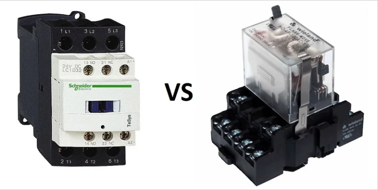
Contactors vs. Relays: What’s the Difference and When to Use Each?
Updated: August 29, 2025
~8 min read • ~1,600 words • Flesch ~60
TL;DR: Use contactors for switching power to motors, heaters, and lighting feeders where current, inrush, and arc energy are high. Pair them with overload protection and verify SCCR. Use relays for control-level logic, signal isolation, and as interposing devices between PLCs and power coils. Match coil voltage, contact ratings, and environment. Follow NEC 2023 Articles 430 and 409 for ratings, overloads, and panel SCCR. When in doubt, call the AHJ.
Why it matters
Pick the wrong device and you cook contacts, nuisance-trip breakers, or stall a motor on a job you needed done yesterday. Contactors and relays look similar but they are built for different work. Contactors are for power. Relays are for control. Getting this right protects gear, keeps inspectors happy, and saves callbacks across Long Island. If you are building a panel or upgrading a starter, you will likely need both. For heavy loads, start your search with industrial contactors suited to the horsepower and voltage you plan to switch.
Fundamentals
What a contactor is
- An electrically operated switch designed to control higher current and power. Think motors, large heaters, and lighting banks.
- Usually shipped with normally open main poles so loads are de-energized at rest. Auxiliary contacts may be NO or NC for interlocks and status.
- Built with arc chutes and larger contact spacing to break inductive loads safely and extend life.
- Rated in horsepower and amperes. North America uses NEMA sizes (00 through 9). IEC devices use utilization categories (for example AC-3 for squirrel-cage motors) and make/break ratings.
- Often paired with an overload relay to form a motor starter that trips on sustained overcurrent.
What a relay is
- An electrically operated switch for control-level tasks. It passes small currents and signals, not feeder power.
- Comes in many contact forms (SPDT, DPDT, 4PDT) for logic and interlocking.
- Used to isolate a delicate controller or PLC output from the field device. The relay takes the abuse, the controller stays safe.
- Can switch AC or DC, but you must check contact ratings for both make/break and continuous current.
Coils and control voltages
Both devices use coils that create a magnetic field to pull in the armature. Coils are sold for common control voltages such as 24 V AC, 24 V DC, 120 V AC, or 240 V AC. The coil voltage must match your control circuit. DC coils often include a suppression diode or RC network. AC coils may include shading rings to reduce chatter on sine waves. Coil inrush can be several times the sealed VA, which matters when sizing PLC outputs or control transformers.
Mechanical and electrical life
- Mechanical life counts operations with no load. Both relays and contactors can hit millions of cycles mechanically.
- Electrical life depends on load type. Inductive loads shorten life. Contactors are tested and rated for tougher duty cycles with defined utilization categories.
NEMA vs IEC quick view
- NEMA contactors are conservatively rated by size. If a motor’s full-load current fits a size, you have margin for typical duty.
- IEC contactors require you to match the utilization category and current to the load. AC-1 is non-inductive. AC-3 covers starting and stopping motors while they run.
Where each fits
- Use a contactor when you are switching a motor, a heater bank, or a lighting circuit with significant current or inrush.
- Use a relay when you need signal-level logic, interlocking, or an interposing stage between a controller and a field device. Browse industrial control relays for panel work and PLC interfaces.
Code & compliance (NEC 2023 refs)
- Motor controllers must be properly rated. NEC 430.83 requires the controller to have suitable horsepower and voltage ratings for the motor. That usually means choosing a contactor or starter with at least the motor’s HP at the applied voltage.
- Overload protection is not optional. NEC 430.32 sets the maximum overload relay setting based on motor service factor and temperature rise. A common case is 125% of nameplate current for SF 1.15 motors. Size heaters or program electronic overloads accordingly.
- Industrial control panels must have an SCCR and be installed within it. NEC 409.22 prohibits installing a panel where available fault current exceeds its marked short-circuit current rating, and 409.110 requires SCCR marking. Keep documentation of available fault current for the inspector.
- Listing and standards. Power contactors and starters are evaluated to UL 60947-4-1, which addresses coordination with upstream protection and defines Type 1 and Type 2 coordination expectations. General-purpose electromechanical relays fall under UL 61810-1. NEMA ICS 2 provides the North American framework for contactor and starter ratings.
Local adoption varies across Long Island jurisdictions. Confirm amendments with the AHJ before you submit or energize.
Selection steps
Use this quick path before you order parts or land wires.
- Define the load. Motor horsepower, voltage, and duty cycle drive contactor selection. Lighting and heaters can be non-inductive; motors are inductive with inrush. For motors, pick by HP and utilization category (for example IEC AC-3) or by NEMA size.
- Pick the control voltage. Match the coil to 24 V DC, 24 V AC, 120 V AC, or 208/240 V AC control. Verify the inrush VA against your control transformer or PLC output capacity. If your controller output is limited, use an interposing general-purpose relay to buffer the coil.
- Decide on contact form and poles. Contactors usually provide 3 poles NO for three-phase loads, with add-on auxiliaries. Relays offer SPDT through 4PDT for logic. Add auxiliary blocks for seal-in, permissives, and status as needed.
- Check SCCR and coordination. Verify the panel SCCR and select combinations that meet Type 1 or Type 2 coordination targets with the upstream OCPD, per UL 60947-4-1 application data. Keep breaker-fuse-contactor tables with the submittal.
- Match the environment. Temperature, vibration, and enclosure rating matter. For rooftop or mechanical rooms, consider definite purpose contactors common in HVAC service. For panel interiors, socket relays speed maintenance.
Sizing/config examples with shown math and rounding
Example 1: 10 hp, 460 V, 3-phase motor starter
Given: Nameplate FLA 14.0 A, service factor 1.15, controller coil 120 V AC.
- Contactor size: Select a device or NEMA size with at least 10 hp at 460 V and AC-3 duty (IEC) or NEMA size that covers 10 hp. Verify main contact rating ≥ 14.0 A running current.
- Overload setting: NEC 430.32 allows up to 125% for SF 1.15. Calculation: 14.0 A × 1.25 = 17.5 A. Round to the nearest available heater or set electronic overload to 17.5 A. Document the setting on the panel schedule.
- Coordination check: Use the manufacturer table to pair the chosen contactor and overload with the upstream breaker or fuses for the desired Type 1 or Type 2 performance. File the table in the job packet.
Example 2: Lighting contactor for a 208 V, 3-phase parking lot circuit
Given: Three 20 A lighting branch circuits fed by a feeder contactor.
- Device: Choose a lighting contactor with at least 60 A total pole rating and coils compatible with your control (often 24 V AC from a time clock or relay panel).
- Poles: 3 poles for the 3-phase feeder. Add an auxiliary contact for status back to the BMS if needed.
- NEC check: Verify SCCR labeling and that the panel’s available fault current does not exceed the marked SCCR per 409.22.
Example 3: PLC output drives interposing relay, which drives a contactor
Given: PLC DO can source only 0.5 A at 24 V DC; contactor coil inrush is 2.0 A at 24 V DC.
- Relay stage: Pick a DIN socket relay with a 24 V DC coil that draws less than 0.5 A inrush. Land the PLC DO on the relay coil.
- Power stage: Use the relay’s NO contact to energize the contactor coil. Confirm relay contact rating exceeds the coil current with margin. For relay compliance, verify UL 61810-1 listings.
Installation & wiring notes
- Coil voltage and polarity: Land AC and DC coils correctly. DC coils may have internal diodes; observe polarity. Label coil voltage on the door legend to prevent misfeeds during service.
- Control power sizing: Add up coil inrush VA and sealed VA for all simultaneously energized devices. Size the control transformer or power supply accordingly. If a PLC output can’t supply inrush, use an interposing stage such as socket relays.
- Auxiliary contacts: Use dedicated auxiliary blocks for seal-in circuits, permissives, and status. Keep power and control conductors separated and identified per panel standard.
- Conductor terminations: Torque lugs to the nameplate values and re-torque after initial thermal cycles if the manufacturer requires it. Use ferrules on fine-strand control wire where listed.
- Surge suppression: Add MOVs, RC snubbers, or flyback diodes across coils to reduce contact wear and PLC input noise. Verify the suppression device’s voltage class matches the coil.
- Mechanical mounting: DIN-rail for relays and smaller IEC contactors; panel-mount for larger NEMA devices. Maintain clearance for arc chutes and heat dissipation.
- Environmental rating: Rooftop and mechanical spaces are hard on gear. For HVAC duty consider definite purpose contactors listed for the temperature range. Use appropriate enclosures and gaskets.
Testing, commissioning, documentation
- Point-to-point check: Verify every wire number against the schematic before energizing. Confirm interlocks and permissives function with power off using a continuity meter.
- Insulation and megger: If required by spec, isolate electronics and test motor or feeder insulation resistance before landing on the contactor.
- Bump test: With load disconnected or uncoupled, momentarily energize the contactor to verify coil pickup, direction of rotation for motors, and auxiliary contact status.
- Overload settings: Record electronic overload parameter values or heater catalog numbers on the panel schedule. Photograph the settings for the turnover package.
- SCCR proof: Keep the available fault current study or utility letter in the job file. Ensure the panel’s marked SCCR is not exceeded. Affix labels where needed.
- As-builts: Update drawings for any field changes. Note coil voltages, relay part numbers, and wiring changes for future service calls.
Troubleshooting
- Coil chatters or won’t pull in: Wrong coil voltage, insufficient power supply, or missing shading ring on AC coils. Measure coil voltage at the terminals during pickup.
- Contacts weld or burn: Load is inductive and exceeds the make/break rating, or no suppression is installed. Upsize the device per utilization category or add suppression.
- Nuisance tripping on motor starts: Overload set too low or wrong class. Recalculate per nameplate amps and service factor. Check for single-phasing or high mechanical load.
- PLC output faulting: Driving a coil directly that exceeds output inrush. Insert an interposing general-purpose relay or a relay module rated for inductive loads.
- Buzzing lighting contactor: Loose laminations or incorrect coil frequency. Replace the coil or the device; verify control power frequency and voltage.
- Random control issues after shutdowns: No suppression across coils or contactor-generated noise feeding back. Add proper MOV/RC/diode components and route control wiring away from power.
Common mistakes
- Using a relay where a contactor is required. If the load has motor inrush or significant inductance, a small relay will burn up. Choose a contactor with the correct utilization category and horsepower rating.
- Mismatched coil voltage. Landing 120 V AC on a 24 V DC coil destroys it. Label coil voltages on the schematic and door card.
- No overload on motors. A contactor alone does not protect a motor from overload. Add an overload relay and set it per nameplate and NEC 430.32.
- Ignoring SCCR. Installing a panel where available fault current exceeds the marked SCCR violates NEC 409.22 and risks catastrophic failure.
- No surge suppression. Unprotected coils generate transients that cause nuisance PLC faults and premature contact wear.
- Forgetting auxiliaries. Seal-in circuits, permissives, and status often require extra contacts. Add the right auxiliary blocks instead of improvising in the field.
Parts to stock + Shop at Revco
- General-purpose and IEC contactors for motors and feeders.
- Definite purpose contactors for HVAC service.
- Lighting contactors for exterior and area lighting.
- Overload relays to pair with contactors for motor protection.
- General-purpose relays for interposing and logic.
- Socket relays and bases for fast swaps.
- Contactor accessories including auxiliary blocks and suppressors.
When to call the AHJ or an engineer
- New or modified industrial control panels. Confirm SCCR marking method, available fault current, and listing requirements with your local AHJ on Long Island before fabrication or energizing.
- Hazardous locations or special occupancies. If Article 500 series or special equipment applies, consult a licensed engineer.
- Uncertain motor loading or duty cycle. When process duty is complex, have an engineer size starters, overload classes, and coordination.
Local amendments vary across towns and villages on Long Island. The AHJ has final say on interpretation and enforcement.
Safety disclaimer
Work only by qualified persons following applicable codes, manufacturer instructions, and job specifications. De-energize and lock out before service. Verify absence of voltage. If you are not sure a relay or contactor is appropriate, stop and review with the AHJ or a professional engineer.
FAQ
- Can a relay run a small motor? Not recommended. Even fractional-horsepower motors have inrush that exceeds relay make ratings. Use a contactor or a starter with an overload.
- Do I need an overload with a contactor? For motors, yes. NEC 430.32 requires overload protection sized from the motor nameplate and service factor.
- What is AC-3? An IEC utilization category for switching squirrel-cage motors while running. Use it when selecting IEC contactors for motor duty.
- Why is my contactor buzzing? Possible wrong coil voltage or frequency, low control voltage, or a damaged shading ring. Check the coil data and supply.
- How do I size a control transformer? Sum the inrush VA of coils that pull in together and add a margin. Compare to the transformer’s VA rating.
- What is panel SCCR? The maximum short-circuit current the panel can safely withstand. Per NEC 409.22 and 409.110, it must be marked and not exceeded at the installation point.
About Revco Lighting & Electrical Supply
Since 1978, Revco Lighting & Electrical Supply has been helping professionals bring their projects to light—literally. As a go-to source for lighting and electrical products across Long Island, NY and nearby areas, we specialize in supporting contractors, builders, and industry experts with practical solutions and dependable service. Whether it’s a complex commercial build or a simple residential upgrade, we’re here to make sure you have what you need, when you need it.
Credits
Author: Revco Editorial Team, Electrical Content Editor
Technical review: Pending: add approved name/credential
Contact: (631) 283-3600
Sources
- NFPA. “NFPA 70: National Electrical Code, 2023 edition.” Retrieved August 2025 from nfpa.org.
- UL. “UL 60947-4-1 Low-voltage switchgear and controlgear — Contactors and motor-starters.” Retrieved August 2025 from ul.com.
- UL. “UL 61810-1 Electromechanical elementary relays — Part 1: General requirements.” Retrieved August 2025 from ul.com.
- NEMA. “ICS 2 Industrial Control and Systems: Controllers, Contactors, and Overload Relays for Motors.” Retrieved August 2025 from nema.org.
Tags: #contactorsvsrelays